Caldwell Guitars Nashville
Valco® BloodBuzz Pedal
Valco® BloodBuzz Pedal
Couldn't load pickup availability
A Note From Valco:
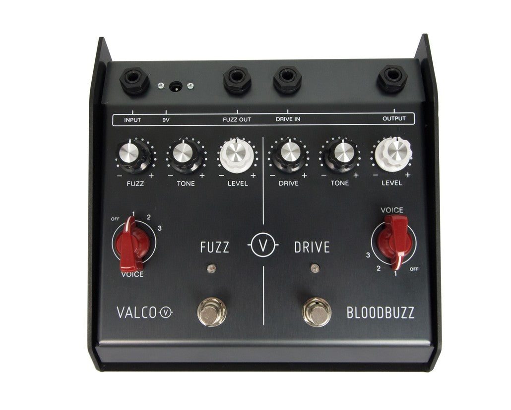
The BloodBuzz FUZZ section input is buffered by a low‐noise JFET op‐amp, with characteristics similar to a vacuum tube amp input. A variable bias dual‐transistor amplifier stage provides the variable drive function (VOICE 3). A silicon bipolar transistor is used in a unique common‐base mode together with a silicon diode to create a warm and complex distortion generating element. The standard tone control circuit is post‐distortion for full effect on the rich harmonic palette. The final output stage uses another JFET op‐amp to provide an additional fixed boost of 9 dB.
A four‐position rotary switch provides a wide range of audio options by switching signal paths and tone shaping components with effects as described in the “Controls” section above.
The DRIVE section has a transistor emitter‐follower at its input. A variable feedback JFET op‐amp drive section provides up to 40 dB of gain with symmetric clipping. When driven hard, this can provide a classic distortion function. The tone section provides a wide range of tone curve settings using a rotary potentiometer and four position selector switch. The output stage uses a low‐noise JFET op‐amp to provide 12 dB of clean signal boost, superior to typical boost pedals.
The FUZZ and DRIVE sections are completely independent and can be used singly or in tandem. Each has its own input and output jack. By default, the FUZZ comes before the DRIVE, with the internal bypass within the “DRIVE IN” jack feeding FUZZ output into DRIVE input without need of an external patch cable. You can place the DRIVE ahead of the FUZZ by plugging the input signal into the “DRIVE IN” jack, connecting a patch cable from “OUTPUT” to “INPUT”, and taking the output from the “FUZZ OUT” jack. Using all four jacks, you can patch the two effects independently into any positions you wish within your pedalboard.
The analog circuitry includes a fully regulated analog ground for maximum immunity form hum, power supply variations and battery aging.
All active components are surface mounted. PCBs and ribbon are cables used throughout. No unreliable point‐to point wiring. Lead and cadmium free construction (RoHS).
To install or replace 9V battery (not included), grab one of the footswitches and use it to lift the top cover of the pedal case up and swing it back. Snap the battery clip onto the battery terminals and place the battery in the spring clip at the inside back left of the housing cover. The battery is connected whenever a plug is inserted into the FUZZ IN or DRIVE IN jack. Be sure to unplug from both those jacks when pedal is not in use.
If an AC adaptor plug (not included) is inserted, the internal battery is disconnected. Replace battery when you detect a loss of signal output level, unusual distortion, or a dimming of the LEDs.
Share


